Thermal gas mass flow meter is designed on the basis of thermal dispersion, and adopts method of constant differential temperature to measuring gas flow. It has advantages of small size, easy installation, high reliability and high accuracy, etc.
The sensor part of the thermal gas mass flow meter consists of two reference platinum resistance. When the flow meter is in the working state, a temperature sensor continuously measures the medium temperature T1. The other sensor will be heated to a temperature T2. And this sensor is a speed sensor to check the flow rate. T2 is greater than T1. There is a temperature difference △T=T2-T1.
When gas flow going through, the gas molecules in the process will take away temperature, so that the value of T2 has been decreased. So if you want to make sure △T unchanged, it must increase the speed sensor power supply current. The greater the velocity of the medium, the greater the power supply current of the speed sensor. At the same time, there is a specific functional relationship between the velocity of the gas and the heat, that is the connotation of the constant temperature difference principle.
V=[K(Q/△T)^1.87]/ρg …………(1)
In the formula:ρg — specific gravity of fluid (related to medium density)
V — Flow rate
K – equilibrium coefficient
Q — heat added (related to specific heat)
△T — temperature difference
Since the sensor temperature is always about 30 ° C higher than the medium (ambient) temperature automatically, the thermal gas mass flow meter does not need temperature compensation in principle.
The thermal gas mass flow meter is suitable for the medium temperature range of -40-220℃.
ρ=ρn*[(101.325+P)/101.325]*[(273.15+20)/(273.15+T)]……(2)
In the formula:ρ — medium density under working conditions (kg/m3)
ρn — medium density under standard conditions (101.325kPa, 20℃) (kg/m3)
P — Operating pressure (kPa)
T — Operating temperature (℃)
As we can see equation (1) and (2), the function of medium flow rate and operating pressure, gas density and operating temperature has been determined.
The thermal mass flow meter using the principle of constant temperature difference, so it needn’t temperature and pressure compensation.
Features
-No pressure and temperature compensation, direct measurement of gas mass flow, simple composition, small probability of failure.
-Wide range ratio (greater than 100:1), convenient loading and unloading, easy to use.
-Fast response, high accuracy, no moving parts, strong structure, vibration resistance.
-High sensitivity, especially suitable for large diameter, low flow rate measurement.
-Scene display, signal output, upper and lower alarm, etc.
-It can be used in high temperature and corrosive environment.
-If site conditions permit, continuous installation and maintenance can be achieved (special customization is required).
Specifications
| Performance |
Technical parameter |
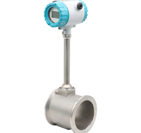
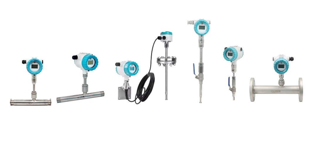
| Structural form |
plug-in |
pipelined |
| Measuring medium |
All gases (except acetylene) |
| Pipe diameter range |
Caliber DN32 or higher |
DN10~DN2000mm |
| Velocity range |
0.1~120Nm/s |
| Precision |
±1~2.5% |
| Operating temperature |
Sensor:-40℃~+220℃ convertor:-20℃~+45℃ |
| Working pressure |
Medium pressure≤2.5Mpa |
Medium pressure≤4.0Mpa |
| Power supply |
DC24V or AC220V≤18W |
| Response speed |
1s |
| Output signal |
4-20mA (Photoelectric isolation, large load 500Ω)、pulse、RS-485 (photoelectric isolation)、HART agreement |
| Alarm |
1-2 relay normally open contact、10A/220V/AC、*/30V/DC |
| Type of supply |
Separate structure, integrated structure |
| Pipe material |
Carbon steel, stainless steel, plastic, etc |
| Field display |
Four lines of Chinese liquid crystal display |
| Display content |
Mass flow, standard volume flow, cumulative flow, standard time, cumulative running time, standard flow rate, etc |
| Protection grade |
IP65 |
| Sensor material |
Stainless steel |
Stainless steel, carbon steel |
Upper Range Value of Common Gas
(Unit: Nm3/h. The follow table can be extended)
| Nominal Diameter (mm) |
Air |
Nitrogen(N2) |
Oxygen(O2) |
Hydrogen(H2) |
| 15 |
65 |
65 |
32 |
10 |
| 25 |
175 |
175 |
89 |
28 |
| 32 |
290 |
290 |
144 |
45 |
| 40 |
450 |
450 |
226 |
70 |
| 50 |
700 |
700 |
352 |
110 |
| 65 |
1200 |
1200 |
600 |
185 |
| 80 |
1800 |
1800 |
900 |
280 |
| 100 |
2800 |
2800 |
1420 |
470 |
| 125 |
4400 |
4400 |
2210 |
700 |
| 150 |
6300 |
6300 |
3200 |
940 |
| 200 |
10000 |
10000 |
5650 |
1880 |
| 250 |
17000 |
17000 |
8830 |
2820 |
| 300 |
25000 |
25000 |
12720 |
4060 |
| 400 |
45000 |
45000 |
22608 |
7200 |
| 500 |
70000 |
70000 |
35325 |
11280 |
| 600 |
100000 |
100000 |
50638 |
16300 |
| 700 |
135000 |
135000 |
69240 |
22100 |
| 800 |
180000 |
180000 |
90432 |
29000 |
| 900 |
220000 |
220000 |
114500 |
77807 |
| 1000 |
280000 |
280000 |
141300 |
81120 |
| 1200 |
400000 |
400000 |
203480 |
91972 |
| 1500 |
600000 |
600000 |
318000 |
101520 |
| 2000 |
700000 |
700000 |
565200 |
180480 |
The flow rate in standard condition: The flow rate is in the condition of 20℃ temperature and 101.325kPa pressure.
The unit of flow rate is optional: Nm3/h, Nm3/min, L/h, L/min, t/h, t/min, kg/h or kg/min.
The reduction formula of flow rate in working condition and flow rate in standard condition:
Qs: The flow rate in standard condition (Nm3/h).
Qn: The flow rate in working condition (m3/h).
t: The medium temperature in working condition (℃).
p: The medium pressure in working condition (Gauge pressure, MPa).