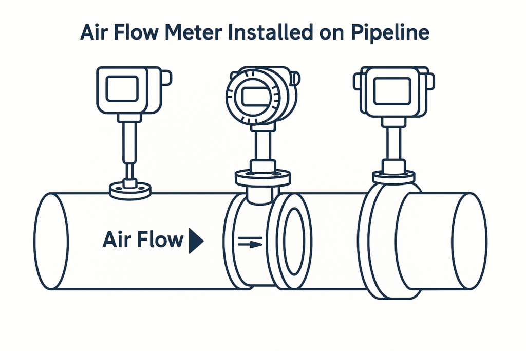
Introduction to Compressed Air Flow Measurement
Compressed air systems represent one of the most widely used industrial utilities, powering everything from pneumatic tools to automated production lines. However, compressed air is also one of the most expensive utilities to generate, with energy costs accounting for approximately 70-80% of the total cost of ownership over a compressed air system’s lifecycle.
Accurate measurement and monitoring of compressed air flow rates have become critical for industrial facilities seeking to optimize energy efficiency, reduce operational costs, and maintain system reliability. A compressed air flow meter serves as the cornerstone technology for achieving these objectives, providing real-time data on consumption patterns, system performance, and potential inefficiencies.
The global compressed air flow meter market has experienced steady growth, driven by increasing industrial automation, stringent energy efficiency regulations, and growing awareness of compressed air system optimization. Modern facilities are implementing comprehensive compressed air monitoring systems that incorporate advanced flow meter technologies to achieve substantial energy savings and operational improvements.
What is a Compressed Air Flow Meter?
A compressed air flow meter is a specialized instrument designed to measure the volumetric or mass flow rate of compressed air within pneumatic systems. Unlike standard gas flow meters, these devices are specifically engineered to handle the unique characteristics of compressed air, including varying pressure levels, temperature fluctuations, and the presence of moisture and contaminants.
Definition and Purpose
Compressed air flow meters quantify the amount of compressed air flowing through a pipeline or system over a specific time period. The measurements are typically expressed in standard cubic feet per minute (SCFM), actual cubic feet per minute (ACFM), or cubic meters per hour (m³/h), depending on regional preferences and application requirements.
The primary purposes of compressed air flow measurement include:
- Energy management: Identifying high-consumption areas and optimization opportunities
- Leak detection: Monitoring baseline consumption to detect system leaks
- Cost allocation: Accurately billing different departments or processes for compressed air usage
- System sizing: Ensuring compressor capacity matches actual demand
- Performance monitoring: Tracking system efficiency over time
Key Characteristics
Modern compressed air flow meters are distinguished by several key characteristics that differentiate them from general-purpose gas flow meters:
Pressure Compensation: Most compressed air applications involve varying pressure conditions, requiring meters with built-in pressure compensation to provide accurate standard flow readings regardless of operating pressure fluctuations.
Temperature Correction: Compressed air systems generate heat during compression, and temperature variations can significantly affect flow readings. Advanced meters incorporate temperature sensors and correction algorithms to maintain accuracy across different operating temperatures.
Moisture Handling: Compressed air systems often contain moisture that can affect measurement accuracy and damage sensitive components. Specialized meters include features to handle condensation and maintain performance in humid conditions.
How Compressed Air Flow Meters Work
Understanding the operating principles of compressed air flow meters is essential for proper selection, installation, and operation. Different meter technologies employ various physical phenomena to detect and quantify flow rates.
Measurement Principles
Differential Pressure Measurement: This traditional approach measures the pressure difference across a flow restriction element such as an orifice plate, venturi tube, or flow nozzle. The pressure differential correlates directly with flow rate according to Bernoulli’s equation:
Q = K × √(ΔP × ρ)
Where:
- Q = Flow rate
- K = Discharge coefficient
- ΔP = Pressure differential
- ρ = Fluid density
Thermal Dispersion Technology: Thermal mass flow meters utilize the heat transfer properties of compressed air to determine mass flow rates. A heated sensor element is exposed to the flowing air stream, and the rate of heat dissipation is proportional to the mass flow rate.
Ultrasonic Transit Time: Ultrasonic meters measure the time difference for ultrasonic pulses traveling upstream and downstream across the pipe. The transit time differential is directly proportional to the flow velocity.
Signal Processing and Output
Modern compressed air flow meters incorporate sophisticated signal processing capabilities to enhance accuracy and provide versatile output options. Digital signal processors (DSP) analyze raw sensor data, apply compensation algorithms, and generate standardized output signals.
[Image: Cross-sectional diagram of a thermal mass flow meter showing sensor elements and flow path]
Common output formats include:
- 4-20 mA analog signals
- Digital pulse outputs
- Modbus RTU/TCP communication
- Ethernet connectivity
- Wireless transmission protocols
Compensation and Correction Algorithms
Advanced compressed air flow meters employ multiple compensation techniques to maintain accuracy across varying operating conditions:
Pressure Compensation: Real-time pressure measurements are used to convert actual flow rates to standard conditions, typically 14.7 PSIA and 70°F.
Temperature Compensation: Integrated temperature sensors provide data for thermal expansion corrections and density calculations.
Humidity Correction: Some high-precision meters incorporate humidity sensors to account for moisture content variations in the compressed air stream.
Types and Classifications of Compressed Air Flow Meters
The selection of appropriate compressed air flow meter technology depends on various factors including accuracy requirements, pressure conditions, pipe size, and budget constraints. Understanding the different types and their characteristics is crucial for making informed decisions.
Thermal Mass Flow Meters
Thermal mass flow meters represent the most popular choice for compressed air measurement applications due to their direct mass flow measurement capability and excellent accuracy across wide flow ranges.
Key features of thermal mass flow meters include:
- Direct mass flow measurement eliminates density calculations
- Wide turndown ratios (typically 100:1 or higher)
- No moving parts, resulting in minimal maintenance requirements
- Excellent low-flow sensitivity
- Built-in temperature and pressure compensation
Applications well-suited for thermal mass flow meters:
- Compressed air system monitoring
- Leak detection programs
- Individual equipment monitoring
- Energy management systems
[Table: Thermal Mass Flow Meter Specifications]
| Parameter | Typical Range | Accuracy |
|---|---|---|
| Flow Range | 0.1-1000 SFPS | ±1-2% of reading |
| Pressure Range | 0-500 PSIG | ±0.25% FS |
| Temperature Range | -40°F to +300°F | ±2°F |
| Turndown Ratio | 100:1 | N/A |
| Response Time | 1-3 seconds | N/A |
Vortex Flow Meters
Vortex flow meters operate on the principle of vortex shedding, where a bluff body placed in the flow stream creates alternating vortices downstream. The frequency of vortex shedding is proportional to the flow velocity.
Advantages of vortex meters for compressed air applications:
- Wide operating range with good accuracy
- No moving parts to wear or maintain
- Relatively low cost compared to other technologies
- Suitable for high-pressure applications
- Digital output proportional to flow rate
Limitations to consider:
- Minimum flow velocity requirements for reliable operation
- Sensitivity to upstream flow disturbances
- Potential issues with very low-density gases
- Vibration sensitivity in some installations
Ultrasonic Flow Meters
Ultrasonic flow meters offer non-intrusive measurement capabilities, making them attractive for retrofit applications where pipe cutting is not feasible. These meters can be classified into clamp-on and insertion types.
Benefits of ultrasonic technology:
- Non-intrusive installation options available
- No pressure loss across the meter
- Wide pipe size range capability
- Bi-directional flow measurement
- Self-diagnostic capabilities
Considerations for compressed air applications:
- Acoustic coupling requirements for clamp-on meters
- Pipe material and condition limitations
- Potential accuracy limitations at low flow rates
- Higher initial cost compared to some alternatives
Differential Pressure Meters
Traditional differential pressure meters continue to serve in many compressed air applications, particularly where cost is a primary consideration or where other technologies face limitations.
[Image: Cutaway view of an orifice plate differential pressure meter installation]
Common differential pressure elements include:
- Orifice plates
- Venturi tubes
- Flow nozzles
- Pitot tubes
Advantages of differential pressure meters:
- Well-established technology with extensive historical data
- Lower initial cost for basic installations
- Wide range of available sizes and configurations
- Suitable for high-pressure applications
- Accepted by most industry standards
Key Features and Components
Modern compressed air flow meters incorporate numerous advanced features and components designed to enhance performance, reliability, and ease of use. Understanding these elements is essential for proper specification and operation.
Sensor Technology
Primary Sensing Elements: The heart of any flow meter is its primary sensing element, which directly interacts with the flowing compressed air to generate a measurable signal. Different technologies employ various sensing principles:
- Thermal sensors: Precision resistance temperature detectors (RTDs) or thermistors for thermal mass flow meters
- Piezoelectric sensors: High-frequency crystals for ultrasonic meters
- Pressure sensors: Differential pressure transducers with silicon diaphragms
- Optical sensors: Laser-based systems for advanced particle detection
Secondary Sensors: Modern meters incorporate multiple secondary sensors to provide compensation and diagnostic information:
- Temperature sensors for thermal compensation
- Pressure sensors for density correction
- Humidity sensors for moisture content monitoring
- Vibration sensors for mechanical diagnostic purposes
Electronics and Signal Processing
Microprocessor Control: Contemporary compressed air flow meters utilize powerful microprocessors to perform complex calculations, implement compensation algorithms, and provide advanced diagnostic capabilities. These processors typically include:
- High-resolution analog-to-digital converters (ADC)
- Digital signal processing capabilities
- Non-volatile memory for configuration storage
- Real-time clock functions for data logging
- Communication interface controllers
Display and Interface: User-friendly interfaces are crucial for effective meter operation and maintenance. Modern meters typically feature:
- LCD or LED displays with multiple parameter views
- Intuitive menu navigation systems
- Local configuration capabilities
- Diagnostic status indicators
- Password protection for critical settings
Communication Capabilities
Standard Communication Protocols: Industrial compressed air flow meters support various communication standards to facilitate integration with control and monitoring systems:
- Modbus RTU: Serial communication for traditional PLC connections
- Modbus TCP: Ethernet-based communication for modern networks
- HART: Highway Addressable Remote Transducer protocol for analog systems
- Profibus: Fieldbus communication for Siemens-based systems
- DeviceNet: CAN-based network for Allen-Bradley systems
Wireless Options: Emerging wireless technologies offer installation flexibility and cost savings:
- Wi-Fi: Standard 802.11 protocols for existing wireless networks
- Bluetooth: Short-range communication for mobile device connectivity
- LoRaWAN: Long-range, low-power communication for distributed systems
- Cellular: 4G/5G connectivity for remote monitoring applications
Mechanical Construction
Housing Materials: Compressed air flow meters must withstand industrial environments while maintaining measurement accuracy. Common housing materials include:
- Aluminum: Lightweight and corrosion-resistant for general applications
- Stainless steel: Superior corrosion resistance for harsh environments
- Cast iron: Cost-effective for non-corrosive applications
- Exotic alloys: Specialized materials for extreme conditions
Ingress Protection: Environmental sealing is critical for reliable operation in industrial settings. Standard IP ratings for compressed air flow meters include:
- IP65: Protection against dust ingress and water jets
- IP67: Protection against temporary immersion
- IP68: Protection against continuous submersion
Technical Specifications and Performance Parameters
Understanding the technical specifications and performance parameters of compressed air flow meters is crucial for proper selection and application. These specifications determine the meter’s suitability for specific operating conditions and accuracy requirements.
Accuracy and Repeatability
Measurement Accuracy: The accuracy of compressed air flow meters varies significantly depending on the technology employed and the specific operating conditions. Accuracy is typically expressed as a percentage of reading or percentage of full scale.
[Table: Accuracy Comparison by Meter Type]
| Meter Type | Accuracy (% of Reading) | Repeatability | Turndown Ratio |
|---|---|---|---|
| Thermal Mass | ±1.0% to ±2.0% | ±0.2% | 100:1 |
| Vortex | ±1.0% to ±1.5% | ±0.1% | 20:1 |
| Ultrasonic | ±1.0% to ±2.0% | ±0.2% | 40:1 |
| Differential Pressure | ±1.0% to ±2.5% | ±0.1% | 4:1 |
| Coriolis | ±0.5% to ±1.0% | ±0.05% | 40:1 |
Factors Affecting Accuracy: Several factors can impact the measurement accuracy of compressed air flow meters:
- Flow Profile: Turbulence and swirl in the flow stream can affect accuracy, requiring adequate straight pipe runs upstream and downstream of the meter
- Temperature Variations: Rapid temperature changes can affect sensor performance and measurement stability
- Pressure Fluctuations: Dynamic pressure variations may impact accuracy, particularly for volumetric measurement technologies
- Contamination: Oil, moisture, and particulates in the compressed air can affect sensor performance over time
Operating Range Specifications
Pressure Range: Compressed air flow meters must be designed to handle the full range of system pressures encountered in typical applications. Standard pressure ranges include:
- Low Pressure: 0-50 PSIG for pneumatic tool applications
- Medium Pressure: 50-200 PSIG for general industrial applications
- High Pressure: 200-500 PSIG for specialized processes
- Extra High Pressure: 500+ PSIG for critical applications
Temperature Range: Operating temperature ranges must accommodate both ambient conditions and the heat generated by air compression:
- Standard Range: -20°F to +200°F (-29°C to +93°C)
- Extended Range: -40°F to +300°F (-40°C to +149°C)
- High Temperature: +300°F to +500°F (+149°C to +260°C)
Flow Range: The measurable flow range depends on the meter technology and size:
- Minimum Detectable Flow: Varies from 0.1 to 5 SFPS depending on technology
- Maximum Flow: Limited by velocity constraints, typically 100-300 SFPS
- Turndown Ratio: The ratio of maximum to minimum measurable flow
Response Time and Dynamic Performance
Response Time: The time required for a compressed air flow meter to respond to flow changes is critical for control applications and leak detection systems. Response times vary by technology:
- Thermal Mass Meters: 1-5 seconds typical
- Vortex Meters: 0.5-2 seconds typical
- Ultrasonic Meters: 0.1-1 second typical
- Differential Pressure: 0.1-0.5 seconds typical
Dynamic Range: The ability to accurately measure rapidly changing flow rates is important for applications with variable demand patterns. Modern digital signal processing enhances dynamic performance through:
- Adaptive filtering algorithms
- Predictive flow calculations
- Noise reduction techniques
- Trend analysis capabilities
Power Requirements and Output Specifications
Power Supply Options: Compressed air flow meters accommodate various power supply configurations:
- 24 VDC: Most common for industrial applications
- 12 VDC: Used for mobile or low-power applications
- 115/230 VAC: Available for permanent installations
- Battery Power: For temporary installations or remote locations
- Loop Power: Derived from 4-20 mA current loops
Output Signal Specifications: Standard output signals facilitate integration with control and monitoring systems:
[Table: Standard Output Signal Specifications]
| Output Type | Signal Range | Accuracy | Load Requirements |
|---|---|---|---|
| 4-20 mA | 4.0-20.0 mA | ±0.1% FS | 0-500 Ω |
| 0-10 VDC | 0.0-10.0 V | ±0.1% FS | >1kΩ |
| Pulse | 0.1-10,000 Hz | ±0.01% | >10kΩ |
| Digital | Various protocols | N/A | Protocol dependent |
Advantages and Benefits
The implementation of compressed air flow meters in industrial facilities provides numerous advantages that extend far beyond simple flow measurement. These benefits contribute to improved operational efficiency, cost reduction, and enhanced system reliability.
Energy Management and Cost Reduction
Energy Consumption Monitoring: Compressed air systems typically consume 10-30% of industrial facility electrical energy. Implementing comprehensive flow measurement enables facilities to:
- Identify high-consumption equipment and processes
- Establish baseline consumption patterns
- Monitor energy efficiency improvements over time
- Implement demand-based control strategies
- Optimize compressor loading and sequencing
Quantifiable Cost Savings: Studies have shown that facilities implementing compressed air monitoring systems achieve average energy savings of 15-25%. For a typical industrial facility with compressed air costs of $50,000 annually, this translates to potential savings of $7,500-$12,500 per year.
Leak Detection and Quantification: Compressed air leaks represent one of the largest sources of waste in pneumatic systems. Advanced thermal mass flow meters enable:
- Continuous monitoring of baseline consumption
- Automated leak detection alerts
- Quantification of leak rates for prioritized repairs
- Verification of repair effectiveness
- Long-term leak trend analysis
Operational Efficiency Improvements
System Optimization: Real-time flow data enables operators to optimize system performance through:
- Right-sizing compressor capacity to match actual demand
- Implementing variable speed drive control based on real consumption
- Balancing distribution system pressure drops
- Optimizing equipment staging and sequencing
- Improving system load factor and efficiency
Predictive Maintenance: Continuous flow monitoring provides valuable data for predictive maintenance programs:
- Early detection of equipment performance degradation
- Trending analysis to predict maintenance requirements
- Optimization of maintenance schedules based on actual usage
- Reduction of unplanned downtime through proactive interventions
[Image: Dashboard screenshot showing compressed air system performance metrics and trends]
Process Control and Quality Improvements
Consistent Process Parameters: Many manufacturing processes require precise compressed air flow rates for optimal quality and efficiency. Flow meters enable:
- Closed-loop flow control for critical processes
- Real-time process optimization based on actual consumption
- Quality assurance through consistent air delivery
- Reduced product defects due to air supply variations
- Enhanced process repeatability and control
Data-Driven Decision Making: Comprehensive flow data supports informed decision-making for:
- Capital equipment investments
- Process improvement initiatives
- Energy efficiency projects
- Facility expansion planning
- Operational cost allocation
Regulatory Compliance and Reporting
Environmental Reporting: Many facilities must report energy consumption and greenhouse gas emissions. Compressed air flow meters provide:
- Accurate energy consumption data for reporting
- Carbon footprint calculations based on actual usage
- Documentation for energy efficiency programs
- Verification of environmental improvement claims
- Support for sustainability initiatives
Industry Standards Compliance: Various industry standards require or recommend compressed air monitoring:
- ISO 50001 Energy Management Systems
- ISO 14001 Environmental Management Systems
- ASME Energy Assessment Standards
- Local utility energy efficiency programs
- Government energy reporting requirements
Limitations and Challenges
While compressed air flow meters offer significant benefits, understanding their limitations and potential challenges is essential for successful implementation and operation. Proper awareness of these factors enables better selection, installation, and maintenance practices.
Technology-Specific Limitations
Thermal Mass Flow Meters: Despite their popularity for compressed air applications, thermal mass flow meters have several limitations:
- Contamination Sensitivity: Oil vapors, moisture, and particulates can coat thermal sensors, affecting accuracy and requiring frequent cleaning
- Calibration Drift: Thermal sensors may experience calibration drift over time, requiring periodic recalibration
- Flow Profile Sensitivity: Performance can be affected by turbulent or asymmetric flow profiles
- Temperature Limitation: Extreme temperatures can affect sensor accuracy and electronic stability
Vortex Flow Meters: These meters face specific challenges in compressed air applications:
- Minimum Flow Requirements: Vortex meters require minimum Reynolds numbers for reliable vortex generation
- Vibration Sensitivity: External vibrations can interfere with vortex detection
- Pressure Drop: The bluff body creates permanent pressure loss in the system
- Turndown Limitations: Lower turndown ratios compared to thermal technologies
Ultrasonic Flow Meters: Ultrasonic technology presents unique challenges:
- Acoustic Coupling: Clamp-on meters require proper acoustic coupling to pipe walls
- Pipe Condition Dependency: Performance affected by pipe material, thickness, and condition
- Installation Complexity: Requires precise sensor positioning and calibration
- Cost Considerations: Generally higher initial cost compared to other technologies
Installation and Environmental Challenges
Straight Pipe Requirements: Most flow meter technologies require adequate straight pipe runs upstream and downstream for accurate measurement:
- Upstream Requirements: Typically 10-20 pipe diameters of straight pipe
- Downstream Requirements: Usually 5-10 pipe diameters minimum
- Space Constraints: Industrial facilities may lack adequate straight pipe runs
- Retrofit Limitations: Existing installations may not accommodate proper placement
Environmental Factors: Harsh industrial environments present ongoing challenges:
- Temperature Fluctuations: Rapid temperature changes affect measurement stability
- Moisture and Condensation: Water dropout can damage electronics and affect accuracy
- Chemical Contamination: Corrosive substances in compressed air can damage sensors
- Electromagnetic Interference: Industrial electrical equipment can interfere with sensitive electronics
[Table: Environmental Challenge Mitigation Strategies]
| Challenge | Impact | Mitigation Strategy |
|---|---|---|
| Temperature Variations | ±2-5% accuracy loss | Thermal insulation, compensation algorithms |
| Moisture Content | Sensor degradation | Drainage systems, moisture-resistant designs |
| Oil Contamination | Sensor fouling | Filtration systems, regular cleaning |
| EMI Interference | Signal noise | Shielded cables, grounding systems |
| Vibration | False readings | Vibration dampening, sensor isolation |
Maintenance and Operational Challenges
Calibration Requirements: Maintaining accuracy requires ongoing attention to calibration:
- Drift Compensation: Sensors may drift over time, requiring periodic verification
- Reference Standard Requirements: Calibration requires traceable reference standards
- Downtime Implications: Calibration procedures may require system shutdown
- Cost Considerations: Professional calibration services represent ongoing costs
Maintenance Accessibility: Some installations present maintenance challenges:
- Physical Access: Meters installed in difficult-to-reach locations
- System Shutdown Requirements: Maintenance may require compressed air system shutdown
- Specialized Tools: Some meters require specialized tools or software for maintenance
- Training Requirements: Maintenance personnel need specific training for different technologies
Economic and Technical Considerations
Total Cost of Ownership: Initial purchase price represents only part of the total investment:
- Installation Costs: Professional installation, piping modifications, electrical work
- Commissioning Expenses: System setup, calibration, and integration
- Operating Costs: Power consumption, communication infrastructure
- Maintenance Costs: Regular calibration, cleaning, and component replacement
Integration Complexity: Modern facilities require sophisticated integration:
- Communication Protocols: Multiple protocols may be required for different systems
- Data Management: Large volumes of data require proper storage and analysis systems
- Software Integration: Meters must integrate with existing SCADA and energy management systems
- Cybersecurity: Network-connected devices introduce potential security vulnerabilities
Comparison with Alternative Flow Measurement Technologies
Selecting the optimal flow measurement technology for compressed air applications requires understanding the relative strengths and weaknesses of available alternatives. This comparison helps engineers and facility managers make informed decisions based on specific application requirements and constraints.
Technology Performance Comparison
Accuracy and Reliability: Different technologies exhibit varying performance characteristics across different operating conditions:
[Table: Comprehensive Technology Comparison]
| Technology | Accuracy | Repeatability | Turndown | Pressure Drop | Maintenance |
|---|---|---|---|---|---|
| Thermal Mass | ±1-2% | ±0.2% | 100:1 | Minimal | Low |
| Vortex | ±1-1.5% | ±0.1% | 20:1 | Low-Medium | Low |
| Ultrasonic | ±1-2% | ±0.2% | 40:1 | None | Medium |
| Differential Pressure | ±1-2.5% | ±0.1% | 4:1 | High | Medium |
| Coriolis | ±0.5-1% | ±0.05% | 40:1 | Medium | Medium |
| Turbine | ±0.5-1% | ±0.1% | 10:1 | Medium | High |
Operating Range Capabilities: Each technology has distinct operating range limitations:
Thermal Mass Flow Meters: Excel in low-flow applications with exceptional sensitivity and wide turndown ratios. However, they may struggle with very high-velocity applications and require careful consideration of contamination effects.
Vortex Flow Meters: Perform well in medium to high-flow applications but require minimum flow velocities for reliable operation. They offer good accuracy and digital output signals but have limited turndown capability.
Ultrasonic Flow Meters: Provide excellent versatility with clamp-on installation options and no pressure drop. However, they may have accuracy limitations at very low flow rates and require proper acoustic coupling.
Cost Considerations
Initial Investment Comparison: The total initial investment includes meter cost, installation expenses, and ancillary equipment:
- Thermal Mass Meters: Medium initial cost with moderate installation complexity
- Vortex Meters: Low to medium initial cost with standard installation requirements
- Ultrasonic Meters: Medium to high initial cost, but potentially lower installation costs for clamp-on versions
- Differential Pressure: Low initial cost but may require additional pressure transmitters and impulse piping
- Coriolis Mass Flow Meters: High initial cost but exceptional accuracy and dual-parameter measurement
Life Cycle Cost Analysis: Total cost of ownership extends beyond initial purchase:
[Video: Life cycle cost analysis demonstration for different flow meter technologies]
Operating Costs: Include power consumption, communication expenses, and operational overhead:
- Power consumption varies from 5-25 watts depending on technology and features
- Communication infrastructure costs for network integration
- Training expenses for operations and maintenance personnel
- Software licensing for advanced diagnostic and analysis capabilities
Maintenance Costs: Ongoing maintenance expenses significantly impact total cost of ownership:
- Calibration services typically cost $500-2000 per meter depending on technology and accuracy requirements
- Component replacement costs vary by technology complexity
- Downtime costs for maintenance activities can be substantial in critical applications
Application-Specific Considerations
Leak Detection Applications: For compressed air leak detection and energy management:
Recommended: Thermal mass flow meters excel due to their low-flow sensitivity, wide turndown ratios, and direct mass measurement capability.
Alternative: Ultrasonic flow meters offer non-intrusive installation for retrofit applications.
High-Pressure Applications: Systems operating above 200 PSIG require robust construction:
Recommended: Differential pressure meters handle high pressures well and are cost-effective.
Alternative: Vortex meters offer good high-pressure performance with digital output.
Critical Process Control: Applications requiring precise flow control and exceptional accuracy:
Recommended: Coriolis mass flow meters provide the highest accuracy and excellent repeatability.
Alternative: Well-calibrated thermal mass flow meters offer good performance at lower cost.
Technology Selection Matrix
Decision Criteria Framework: Selecting optimal technology requires evaluating multiple criteria:
Primary Factors:
- Accuracy requirements
- Flow range and turndown needs
- Pressure and temperature conditions
- Installation constraints
- Budget limitations
Secondary Factors:
- Maintenance requirements
- Communication needs
- Environmental conditions
- Existing system compatibility
- Future expansion plans
Application Examples:
Large Industrial Facility Energy Management:
- Technology: Thermal mass flow meters
- Rationale: Wide turndown, low maintenance, direct mass measurement
- Typical Savings: 15-25% energy reduction
Critical Manufacturing Process Control:
- Technology: Coriolis mass flow meters
- Rationale: Highest accuracy, excellent repeatability, dual-parameter measurement
- Typical Performance: ±0.5% accuracy, ±0.05% repeatability
Retrofit Monitoring Installation:
- Technology: Clamp-on ultrasonic meters
- Rationale: Non-intrusive installation, no system shutdown required
- Typical Installation: 2-4 hours per meter location
Selection and Buying Guide
Selecting the appropriate compressed air flow meter requires systematic evaluation of technical requirements, operational constraints, and economic considerations. This comprehensive guide provides a structured approach to making optimal technology and vendor selections.
Requirements Assessment
Flow Measurement Objectives: Clearly define the primary purposes for flow measurement:
Energy Management: Focus on accuracy across wide flow ranges, long-term stability, and integration with energy management systems. Recommended features include:
- Wide turndown ratios (50:1 or better)
- Built-in pressure and temperature compensation
- Data logging capabilities
- Communication protocols for SCADA integration
- Low maintenance requirements
Process Control: Emphasize measurement accuracy, fast response times, and reliable control signals:
- High accuracy (±1% or better)
- Fast response times (1 second or less)
- 4-20 mA analog outputs with HART protocol
- Fail-safe operation modes
- Redundancy options for critical applications
Cost Allocation: Prioritize accuracy, data integrity, and audit trail capabilities:
- Measurement uncertainty within ±2%
- Tamper-evident designs
- Data logging with time stamps
- Communication security features
- Calibration traceability documentation
System Requirements Analysis: Document the specific operating conditions and constraints:
[Table: System Requirements Checklist]
| Parameter | Specification | Impact on Selection |
|---|---|---|
| Flow Range | Min/Max SCFM | Determines meter size and technology |
| Pressure Range | Operating PSIG | Affects meter construction requirements |
| Temperature Range | Operating °F | Influences sensor technology selection |
| Pipe Size | Inches/mm | Determines meter sizing and installation |
| Accuracy Requirements | % of reading | Drives technology selection |
| Installation Constraints | Space limitations | Affects meter type and configuration |
| Power Availability | VDC/VAC options | Determines power supply requirements |
| Communication Needs | Protocols required | Influences electronic specifications |
Technology Selection Process
Performance Requirements Evaluation: Match meter capabilities to application needs:
High-Accuracy Applications (±1% or better):
- First Choice: Coriolis mass flow meters for ultimate accuracy
- Alternative: Thermal mass flow meters with premium calibration
- Consideration: Higher initial cost but superior long-term performance
Wide Turndown Requirements (>20:1):
- Primary Recommendation: Thermal mass flow meters (100:1 typical)
- Secondary Option: Ultrasonic meters (40:1 typical)
- Avoid: Differential pressure meters (4:1 typical limitation)
Low-Flow Sensitivity Applications:
- Optimal Choice: Thermal mass flow meters
- Advantage: Excellent sensitivity to small flow changes
- Benefit: Early leak detection capabilities
Budget-Conscious Applications:
- Cost-Effective: Vortex meters for medium to high flows
- Alternative: Differential pressure meters with electronic transmitters
- Consideration: Balance initial cost against accuracy requirements
Vendor Evaluation Criteria
Technical Capabilities: Assess vendor technical expertise and support:
Engineering Support: Evaluate vendor capabilities in:
- Application engineering assistance
- Custom configuration services
- Integration support and testing
- Commissioning and startup services
- Technical training programs
Product Quality: Consider manufacturing standards and quality systems:
- ISO 9001 quality management certification
- Calibration laboratory accreditation
- Product testing and validation procedures
- Quality assurance documentation
- Warranty terms and conditions
Service and Support: Evaluate long-term support capabilities:
- Local technical support availability
- Response time commitments
- Spare parts availability and pricing
- Repair and calibration services
- Software updates and enhancements
Economic Analysis
Total Cost of Ownership Calculation: Develop comprehensive cost models including:
[Table: Cost Analysis Worksheet]
| Cost Category | Year 1 | Year 2-5 | Year 6-10 | Total |
|---|---|---|---|---|
| Initial Purchase | $5,000 | $0 | $0 | $5,000 |
| Installation | $2,000 | $0 | $0 | $2,000 |
| Commissioning | $1,500 | $0 | $0 | $1,500 |
| Annual Maintenance | $500 | $2,000 | $2,500 | $5,000 |
| Calibration | $0 | $2,000 | $2,000 | $4,000 |
| Power Consumption | $200 | $800 | $1,000 | $2,000 |
| Total | $9,200 | $4,800 | $5,500 | $19,500 |
Return on Investment Analysis: Calculate payback periods based on expected savings:
- Energy cost reductions from leak detection and system optimization
- Maintenance cost savings through predictive maintenance
- Process efficiency improvements and quality enhancements
- Reduced downtime and emergency repair costs
- Regulatory compliance cost avoidance
Installation and Setup Requirements
Proper installation is critical for achieving optimal performance and long-term reliability from compressed air flow meters. This section provides comprehensive guidance on installation planning, execution, and commissioning procedures.
Pre-Installation Planning
Site Survey and Assessment: Conduct thorough evaluation of installation locations:
Piping System Analysis: Document existing piping configuration including:
- Pipe material, size, and wall thickness
- Insulation and external coatings
- Accessibility for installation and maintenance
- Proximity to other equipment and interference sources
- Available straight pipe runs upstream and downstream
Environmental Conditions: Assess installation environment factors:
- Ambient temperature range and variations
- Humidity levels and condensation potential
- Chemical exposure and corrosive atmosphere
- Vibration sources and mechanical stress
- Electrical interference and grounding requirements
Infrastructure Requirements: Verify availability of supporting infrastructure:
- Electrical power supply and distribution
- Communication network connectivity
- Mounting hardware and support structures
- Safety systems and emergency procedures
- Access platforms and maintenance facilities
Installation Procedures
Mechanical Installation: Follow manufacturer specifications for proper mechanical mounting:
Insertion Meters: For meters that require insertion into the pipe:
- Mark insertion depth according to pipe size and manufacturer specifications
- Install isolation valve and retraction mechanism if specified
- Ensure proper sensor orientation and alignment
- Apply appropriate thread sealant or gasket materials
- Torque connections to specified values
Inline Meters: For meters installed directly in the pipe run:
- Ensure adequate straight pipe runs upstream and downstream
- Install with proper flow direction orientation
- Provide adequate support to prevent pipe stress
- Install bypass valving if required for maintenance
- Apply appropriate gasket materials and joint sealants
[Image: Proper installation configuration showing straight pipe requirements and meter positioning]
Clamp-On Meters: For non-intrusive ultrasonic installations:
- Select optimal pipe section with uniform wall thickness
- Prepare pipe surface by removing insulation and cleaning
- Apply acoustic coupling compound as specified
- Install transducers with proper spacing and alignment
- Secure sensor cables and provide strain relief
Electrical Installation
Power Supply Connections: Install appropriate power supply systems:
DC Power Systems: Most compressed air flow meters operate on 24 VDC power:
- Install regulated power supplies with adequate capacity
- Provide proper grounding and electrical isolation
- Use appropriate cable types for industrial environments
- Install surge protection and overcurrent protection
- Document wiring diagrams and connection points
Signal Wiring: Install signal cables according to best practices:
- Use shielded cables for analog signals to minimize interference
- Maintain separation from power cables and high-current conductors
- Install proper cable supports and strain relief
- Provide adequate service loops for maintenance access
- Label all cables and termination points clearly
Communication Networks: Connect meters to control and monitoring systems:
- Configure network addresses and communication parameters
- Test communication links and verify data transmission
- Install network infrastructure equipment as required
- Implement cybersecurity measures for network-connected devices
- Document network configuration and troubleshooting procedures
Commissioning and Startup
Initial Configuration: Program meter settings for specific application:
Basic Parameters: Configure fundamental operating parameters:
- Flow units and engineering scale factors
- Pressure and temperature compensation settings
- Output signal ranges and scaling
- Display preferences and local indication
- Alarm and diagnostic settings
Advanced Settings: Configure application-specific features:
- Damping and filtering parameters for stable operation
- Totalizer and batch functions if required
- Data logging intervals and storage capacity
- Communication protocol settings and addresses
- Security access codes and user permissions
Calibration Verification: Verify measurement accuracy:
- Perform zero flow verification with flow stopped
- Conduct span verification using reference flow standards
- Check linearity across the measurement range
- Verify temperature and pressure compensation
- Document calibration results and certificates
[Video: Complete commissioning procedure demonstration for thermal mass flow meter]
Performance Testing: Validate system performance:
- Test all output signals and communication functions
- Verify alarm and diagnostic operations
- Conduct leak simulation tests if applicable
- Check integration with control and monitoring systems
- Perform acceptance testing according to specifications
Operation and Best Practices
Effective operation of compressed air flow meters requires understanding proper operating procedures, routine monitoring practices, and performance optimization techniques. This section provides comprehensive guidance for maximizing meter performance and system reliability.
Operating Procedures
Startup Procedures: Follow systematic startup sequence for reliable operation:
Pre-Startup Checks: Verify system readiness before energizing equipment:
- Confirm all installation work is complete and properly documented
- Verify electrical connections and grounding systems
- Check mechanical mounting and pipe connections
- Confirm communication network connectivity
- Review safety procedures and emergency shutdown protocols
Initial Startup Sequence: Follow proper sequence to avoid equipment damage:
- Apply power and verify normal startup indication
- Allow stabilization period for thermal equilibrium
- Verify zero flow reading with no flow condition
- Gradually introduce flow and monitor response
- Check all output signals and communication functions
Normal Operating Procedures: Establish routine operating practices:
- Monitor key performance indicators regularly
- Review diagnostic status messages and alarms
- Maintain operation log books with key parameters
- Perform routine visual inspections of equipment
- Follow established procedures for parameter changes
Performance Monitoring
Key Performance Indicators: Monitor critical parameters for optimal performance:
Primary Measurements: Track fundamental flow measurement parameters:
- Flow rate readings and trends over time
- Totalizer values and consumption patterns
- Temperature and pressure compensation values
- System efficiency calculations and benchmarks
- Alarm frequency and diagnostic messages
Secondary Parameters: Monitor supporting measurements for system health:
- Sensor temperature readings and stability
- Power consumption and electrical parameters
- Communication status and data quality indicators
- Environmental conditions and their effects
- Calibration drift indicators and timing
[Table: Performance Monitoring Checklist]
| Parameter | Frequency | Normal Range | Action Required |
|---|---|---|---|
| Flow Rate | Continuous | Design range | Investigate deviations |
| Temperature | Daily | ±5°F of setpoint | Check compensation |
| Pressure | Daily | Design pressure ±10% | Verify system operation |
| Diagnostics | Weekly | No active alarms | Address all warnings |
| Calibration | Annually | Within specification | Schedule recalibration |
Trending and Analysis: Implement systematic data analysis procedures:
- Establish baseline performance benchmarks
- Identify normal operating patterns and cycles
- Detect gradual performance degradation trends
- Compare actual performance against design specifications
- Generate regular performance reports and summaries
Optimization Techniques
System Efficiency Improvements: Implement strategies to maximize system performance:
Flow Profile Optimization: Ensure optimal flow conditions for accurate measurement:
- Maintain adequate straight pipe runs as specified
- Install flow straighteners if necessary for disturbed flows
- Monitor and address sources of flow turbulence
- Optimize piping configuration to minimize pressure drops
- Consider flow conditioning devices for challenging installations
Environmental Control: Manage environmental factors affecting performance:
- Control temperature variations through insulation or heating
- Implement moisture management systems to prevent condensation
- Protect equipment from vibration and mechanical stress
- Maintain proper grounding and electrical isolation
- Shield sensitive electronics from electromagnetic interference
Calibration Management: Maintain measurement accuracy through proper calibration practices:
- Establish calibration schedules based on application criticality
- Use traceable reference standards for all calibrations
- Document calibration procedures and maintain records
- Implement drift monitoring between calibration intervals
- Consider in-situ calibration techniques where applicable
Integration with Control Systems
SCADA Integration: Connect compressed air flow meters to supervisory control systems:
Data Acquisition: Configure data collection and storage systems:
- Set appropriate data sampling rates for application needs
- Implement data validation and quality checks
- Configure alarm limits and notification systems
- Establish data backup and archive procedures
- Integrate with existing energy management systems
Control Applications: Utilize flow measurement data for automatic control:
- Implement demand-based compressor control strategies
- Configure automatic leak detection and notification systems
- Develop energy optimization algorithms based on real-time data
- Integrate with facility automation and building management systems
- Establish predictive maintenance scheduling based on usage patterns
Reporting and Analytics: Generate meaningful reports from flow measurement data:
- Create automated energy consumption reports
- Develop cost allocation reports for different departments
- Generate efficiency trending and benchmarking reports
- Implement predictive analytics for maintenance planning
- Provide regulatory compliance documentation and reporting
Maintenance and Troubleshooting
Proper maintenance is essential for ensuring long-term accuracy, reliability, and service life of compressed air flow meters. This section provides comprehensive guidance on preventive maintenance procedures, troubleshooting techniques, and repair practices.
Preventive Maintenance Programs
Routine Maintenance Tasks: Establish systematic maintenance procedures:
Daily Inspection Items: Quick checks performed during routine operations:
- Visual inspection of meter housing and connections
- Verification of display readings and normal operation
- Check for unusual noises, vibrations, or physical damage
- Review diagnostic messages and alarm status
- Document any abnormal conditions or changes
Weekly Maintenance Tasks: More detailed inspection and verification procedures:
- Clean display windows and external surfaces
- Check electrical connections and cable condition
- Verify communication system operation and data transmission
- Review trending data for unusual patterns or drift
- Inspect mounting hardware and pipe connections
Monthly Maintenance Activities: Comprehensive system checks and testing:
- Perform zero flow verification tests
- Check calibration stability using reference methods
- Inspect and clean sensor elements as required
- Verify alarm and safety system functions
- Update maintenance logs and documentation
[Table: Preventive Maintenance Schedule]
| Task | Frequency | Duration | Personnel Required |
|---|---|---|---|
| Visual Inspection | Daily | 5 minutes | Operator |
| Display Cleaning | Weekly | 10 minutes | Technician |
| Connection Check | Monthly | 30 minutes | Technician |
| Calibration Verification | Quarterly | 2 hours | Specialist |
| Full Calibration | Annually | 4 hours | Certified Technician |
13.2 Calibration Procedures
Calibration Planning: Develop systematic calibration management:
Reference Standards: Establish traceable calibration standards:
- Primary standards: Master meters with certified accuracy
- Secondary standards: Working standards for routine verification
- Portable calibrators: Field-deployable calibration equipment
- Documentation: Maintain calibration certificates and traceability
- Scheduling: Plan calibrations to minimize system downtime
Calibration Procedures: Follow systematic calibration protocols:
Pre-Calibration Checks: Verify system readiness:
- Review maintenance history and previous calibration records
- Inspect meter condition and verify proper installation
- Check environmental conditions and system stability
- Verify reference standard calibration and certification
- Prepare calibration documentation and forms
Calibration Execution: Perform systematic calibration sequence:
- Establish zero flow condition and verify zero reading
- Apply known flow rates across the measurement range
- Record meter readings at each calibration point
- Calculate measurement errors and uncertainty values
- Adjust meter calibration if necessary and within limits
Post-Calibration Activities: Complete calibration documentation:
- Verify proper meter operation after calibration adjustments
- Update meter configuration and calibration factors
- Complete calibration certificates and documentation
- Update maintenance management system records
- Schedule next calibration based on drift characteristics
Troubleshooting Procedures
Systematic Troubleshooting Approach: Follow logical diagnostic procedures:
Problem Identification: Document symptoms and operating conditions:
- Record specific error messages or fault codes
- Note environmental conditions when problems occur
- Document recent changes to system or configuration
- Identify affected measurement parameters or outputs
- Collect diagnostic data and system logs
Common Problems and Solutions: Address typical operational issues:
Measurement Accuracy Issues:
- Symptom: Readings consistently high or low
- Causes: Calibration drift, sensor contamination, installation problems
- Solutions: Recalibration, sensor cleaning, flow profile improvement
- Prevention: Regular calibration, filtration systems, proper installation
Communication Problems:
- Symptom: Loss of communication or intermittent data
- Causes: Network issues, cable problems, configuration errors
- Solutions: Check connections, verify settings, test communication links
- Prevention: Regular cable inspection, proper installation practices
Environmental Issues:
- Symptom: Erratic readings or frequent alarms
- Causes: Temperature effects, moisture problems, vibration
- Solutions: Environmental controls, sensor protection, isolation mounting
- Prevention: Proper site selection, environmental monitoring
[Image: Troubleshooting flowchart showing diagnostic decision tree for common problems]
Repair and Replacement
Component Replacement: Handle component failures systematically:
Sensor Replacement: Follow proper procedures for critical components:
- Document existing configuration and calibration data
- Obtain proper replacement parts with matching specifications
- Follow manufacturer procedures for safe removal and installation
- Perform complete calibration after component replacement
- Update maintenance records with replacement information
Electronics Replacement: Handle electronic component failures:
- Power down system safely and verify lockout procedures
- Document existing configuration settings and parameters
- Install replacement electronics with proper ESD protection
- Restore configuration settings and verify proper operation
- Perform functional testing of all inputs and outputs
Upgrade Considerations: Plan for technology improvements:
- Evaluate benefits of upgrading to newer technology
- Consider improved accuracy, features, or communication capabilities
- Plan upgrade projects to minimize system downtime
- Provide training for new equipment operation and maintenance
- Update documentation and procedures for new equipment
Cost Analysis and Return on Investment
Understanding the economic aspects of compressed air flow meter implementation is crucial for justifying investments and maximizing returns. This section provides comprehensive analysis of costs, savings potential, and financial benefits.
Total Cost of Ownership Analysis
Initial Investment Components: Comprehensive cost breakdown for flow meter projects:
[Table: Initial Investment Cost Breakdown]
| Cost Component | Typical Range | Percentage of Total |
|---|---|---|
| Flow Meter Hardware | $3,000-$15,000 | 40-60% |
| Installation Labor | $1,000-$5,000 | 15-25% |
| Electrical/Communication | $500-$2,500 | 8-15% |
| Commissioning | $500-$2,000 | 5-12% |
| Training | $500-$1,500 | 3-8% |
| Project Management | $500-$2,000 | 5-10% |
| Total Initial Investment | $6,000-$28,000 | 100% |
Operating Costs: Ongoing expenses throughout equipment lifecycle:
Annual Operating Expenses: Regular costs for system operation:
- Power consumption: $50-$200 per meter annually
- Communication services: $100-$500 for network connectivity
- Software licensing: $200-$1,000 for advanced analytics
- Insurance and risk management: 1-2% of equipment value
- Administrative overhead: $200-$500 annually
Maintenance Costs: Regular and periodic maintenance expenses:
- Routine maintenance: $200-$800 annually
- Calibration services: $500-$2,000 every 1-2 years
- Component replacement: $300-$1,500 every 3-5 years
- Emergency repairs: $500-$3,000 per incident
- Upgrade and modernization: 10-20% of initial cost every 10 years
Savings and Benefits Quantification
Energy Cost Savings: Primary source of economic benefits from flow measurement:
Leak Detection Savings: Quantifiable benefits from identifying and repairing system leaks:
- Typical leak rates: 10-30% of total compressed air production
- Energy cost of leaks: $2,000-$10,000 annually for typical facilities
- Leak detection effectiveness: 70-90% reduction in leak rates
- Annual savings potential: $1,500-$9,000 from leak elimination
System Optimization Savings: Benefits from improved system efficiency:
- Compressor efficiency improvements: 5-15% energy reduction
- Pressure optimization: 2-8% energy savings per PSI reduction
- Load management: 10-25% reduction in energy costs
- Equipment right-sizing: 15-40% savings on new equipment
[Table: Energy Savings Calculation Example]
| Facility Parameter | Current State | Optimized State | Annual Savings |
|---|---|---|---|
| Compressed Air Cost | $50,000 | $37,500 | $12,500 |
| Leak Rate | 25% | 5% | $8,000 |
| System Efficiency | 75% | 85% | $3,500 |
| Peak Demand Charges | $15,000 | $12,000 | $3,000 |
| Total Annual Savings | $27,000 |
Operational Benefits: Additional cost savings and productivity improvements:
Maintenance Cost Reduction: Predictive maintenance benefits:
- Reduced unplanned downtime: $5,000-$25,000 annually
- Extended equipment life: 15-25% improvement
- Optimized maintenance scheduling: 10-20% cost reduction
- Improved spare parts management: 5-15% inventory reduction
Process Efficiency Improvements: Manufacturing and quality benefits:
- Reduced product defects due to consistent air pressure
- Improved equipment performance and reliability
- Enhanced process control and repeatability
- Reduced warranty claims and customer complaints
Return on Investment Calculations
Payback Period Analysis: Calculate time to recover initial investment:
Simple Payback Calculation: Payback Period = Initial Investment / Annual Savings
Example Calculation:
- Initial Investment: $15,000 for comprehensive monitoring system
- Annual Savings: $12,000 from energy optimization
- Simple Payback: 15,000 / 12,000 = 1.25 years
Net Present Value Analysis: Consider time value of money:
NPV Calculation Parameters:
- Discount rate: 8-12% typical for industrial projects
- Project life: 10-15 years for flow measurement systems
- Annual cash flows: Energy savings minus operating costs
- Terminal value: Residual equipment value at project end
[Table: 10-Year NPV Analysis Example]
| Year | Initial Cost | Operating Cost | Energy Savings | Net Cash Flow | Present Value |
|---|---|---|---|---|---|
| 0 | ($15,000) | $0 | $0 | ($15,000) | ($15,000) |
| 1-2 | $0 | ($1,000) | $12,000 | $11,000 | $19,174 |
| 3-5 | $0 | ($1,500) | $13,000 | $11,500 | $26,234 |
| 6-10 | $0 | ($2,000) | $14,000 | $12,000 | $32,446 |
| NPV | $62,854 |
Financial Justification Strategies
Business Case Development: Create compelling financial justifications:
Risk Mitigation Benefits: Quantify risk reduction value:
- Avoided costs from system failures and downtime
- Insurance premium reductions for improved safety
- Regulatory compliance cost avoidance
- Environmental liability reduction
Strategic Benefits: Consider long-term strategic advantages:
- Improved competitiveness through cost reduction
- Enhanced sustainability and environmental performance
- Technology platform for future expansion
- Data foundation for Industry 4.0 initiatives
Financing Options: Explore alternative financing approaches:
- Equipment leasing to preserve capital
- Performance contracting with guaranteed savings
- Utility rebates and incentive programs
- Government grants for energy efficiency projects
Industry Applications and Case Studies
Compressed air flow meters find applications across diverse industries, each with unique requirements and challenges. This section examines specific applications and presents detailed case studies demonstrating successful implementations.
Manufacturing Industries
Automotive Manufacturing: Critical applications for precision and efficiency:
Production Line Monitoring: Flow meters enable optimization of pneumatic systems:
- Assembly line tool monitoring for consistent torque specifications
- Paint booth air flow control for quality finish application
- Conveyor system pneumatic controls for material handling
- Brake and suspension testing equipment air supply verification
- Clean room air flow monitoring for contamination control
Case Study: Major Automotive Plant Energy Optimization:
- Facility: 2.5 million square foot assembly plant
- Challenge: $850,000 annual compressed air costs with suspected inefficiencies
- Solution: 45 thermal mass flow meters installed throughout facility
- Results: 28% energy cost reduction saving $238,000 annually
- Payback: 14 months on $82,000 investment
Food and Beverage Processing: Sanitary and precision applications:
Process Applications: Critical flow measurement for food safety:
- Pneumatic conveying systems for ingredient handling
- Packaging equipment air supply for consistent operation
- Cleaning system air flow for CIP (Clean-In-Place) operations
- Fermentation tank pressure control air supply
- Quality control testing equipment air supply
Pharmaceutical Manufacturing: High precision and validation requirements:
Critical Applications: Stringent accuracy and documentation needs:
- Tablet coating equipment air flow control
- Sterile filling line compressed air monitoring
- Laboratory instrument air supply verification
- Clean room differential pressure control
- Validation protocol documentation for regulatory compliance
Process Industries
Chemical Processing: Challenging environments with specialized requirements:
Safety-Critical Applications: Flow measurement in hazardous locations:
- Reactor cooling system air supply monitoring
- Emergency shutdown system pneumatic controls
- Catalyst regeneration air flow measurement
- Flare system purge air monitoring
- Instrument air supply backup systems
[Video: Chemical plant compressed air monitoring system installation and operation]
Petrochemical Refineries: High-pressure and extreme temperature applications:
Refinery Applications: Robust measurement solutions required:
- Crude oil pumping system pneumatic controls
- Distillation column instrument air supply
- Catalyst handling pneumatic conveying systems
- Steam reforming process air flow measurement
- Maintenance tool air supply monitoring
Case Study: Refinery Compressed Air System Optimization:
- Facility: 250,000 barrel per day refinery
- Challenge: Aging compressed air system with high maintenance costs
- Solution: Comprehensive monitoring with 60 flow meters and centralized control
- Technology: Mix of vortex and thermal mass flow meters based on application
- Results: 32% reduction in energy costs and 45% reduction in maintenance
- Additional Benefits: Improved safety and environmental compliance
Utilities and Infrastructure
Power Generation: Critical utility applications:
Power Plant Applications: Reliability and accuracy requirements:
- Coal handling pneumatic conveying systems
- Ash handling compressed air systems
- Instrument air systems for control valves
- Cooling tower air flow monitoring
- Maintenance shop compressed air distribution
Water and Wastewater Treatment: Environmental and efficiency applications:
Treatment Plant Applications: Process optimization and efficiency:
- Aeration system air flow control for biological treatment
- Pneumatic valve actuator air supply monitoring
- Chemical feed system air supply verification
- Sludge handling pneumatic conveying systems
- Laboratory air supply for testing equipment
Commercial Buildings and Facilities
Healthcare Facilities: Critical air quality and reliability requirements:
Medical Air Systems: Life-safety critical applications:
- Medical air compressor system monitoring
- Operating room air supply verification
- Laboratory fume hood air flow measurement
- Sterilization equipment air supply monitoring
- Emergency backup system air flow verification
Data Centers: Precision cooling and environmental control:
Cooling System Applications: Energy efficiency and reliability focus:
- Pneumatic damper control air supply
- Cooling system maintenance air supply
- Precision cooling equipment air flow verification
- Backup system air supply monitoring
- Energy optimization and reporting systems
Specialized Applications
Aerospace and Defense: High precision and reliability requirements:
Critical Applications: Mission-critical performance needs:
- Aircraft testing facility compressed air systems
- Clean room air flow monitoring for satellite assembly
- Wind tunnel compressed air supply systems
- Test equipment air supply verification
- Quality control testing air supply monitoring
Research and Development: Precision measurement for experimental work:
Laboratory Applications: High accuracy and flexibility needs:
- Research equipment air supply monitoring
- Calibration laboratory reference air systems
- Environmental chamber air flow control
- Material testing equipment air supply
- Prototype testing air supply verification
[Image: Research laboratory compressed air monitoring system with multiple flow meters]
Mining and Extraction: Harsh environment applications:
Mining Applications: Rugged and reliable measurement solutions:
- Pneumatic conveying systems for material handling
- Dust suppression system air flow monitoring
- Drilling equipment air supply verification
- Ventilation system air flow measurement
- Safety system compressed air monitoring
Integration with Control Systems
Modern compressed air flow meters must integrate seamlessly with facility control and monitoring systems to provide maximum value. This section covers integration strategies, communication protocols, and system architecture considerations.
Communication Protocols and Interfaces
Industrial Communication Standards: Overview of common protocols used in compressed air monitoring:
Modbus Protocol Family: Most widely adopted industrial communication standard:
- Modbus RTU: Serial communication over RS-485 networks
- Modbus TCP: Ethernet-based communication for modern networks
- Advantages: Universal compatibility, simple implementation, extensive device support
- Applications: Integration with PLCs, SCADA systems, and energy management systems
- Considerations: Limited bandwidth for large systems, security vulnerabilities
Ethernet-Based Protocols: Modern high-speed communication options:
- Ethernet/IP: Allen-Bradley and Rockwell Automation standard
- Profinet: Siemens industrial Ethernet protocol
- EtherCAT: Real-time Ethernet for high-performance applications
- Benefits: High-speed data transfer, advanced diagnostics, web-based interfaces
- Requirements: Managed network infrastructure, cybersecurity considerations
Fieldbus Systems: Traditional industrial network standards:
- Foundation Fieldbus: Process industry standard with power over bus
- DeviceNet: CAN-based network for Allen-Bradley systems
- Profibus: European standard for distributed I/O and drives
- Legacy Considerations: Existing installations, migration strategies
SCADA and HMI Integration
Supervisory Control and Data Acquisition: Connecting flow meters to facility monitoring systems:
Data Point Configuration: Setting up flow meter data in SCADA systems:
- Real-time flow rate measurements and totalized values
- Temperature and pressure compensation parameters
- Diagnostic status information and alarm conditions
- Historical trending data and statistical calculations
- Energy consumption calculations and cost allocation
Alarm and Event Management: Implementing comprehensive monitoring:
- High and low flow rate alarms for leak detection
- Equipment failure notifications and diagnostic alerts
- Calibration due dates and maintenance reminders
- Communication failure detection and recovery procedures
- Historical alarm logging and reporting capabilities
Human Machine Interface Design: Creating effective operator interfaces:
- Real-time dashboard displays with key performance indicators
- Trending charts showing consumption patterns over time
- Equipment status displays with diagnostic information
- Control interfaces for setpoint changes and system configuration
- Mobile-friendly displays for remote monitoring and control
[Table: SCADA Integration Requirements]
| Function | Data Points | Update Rate | Storage Requirements |
|---|---|---|---|
| Real-time Monitoring | 4-8 per meter | 1-10 seconds | 30 days minimum |
| Historical Trending | 2-4 per meter | 1-15 minutes | 2-5 years |
| Alarm Management | 6-12 per meter | Immediate | 1-2 years |
| Reporting | Calculated | Hourly/Daily | 5-10 years |
Energy Management System Integration
Building Management Systems: Integrating with facility automation:
BACnet Integration: Building automation standard protocol:
- Standardized data objects for flow measurement
- Integration with HVAC and lighting control systems
- Energy optimization algorithms using real-time flow data
- Automated reporting for energy management programs
- Integration with utility demand response programs
Energy Information Systems: Connecting to enterprise energy management:
- Automated data collection from multiple flow meters
- Energy cost calculation and allocation by department
- Benchmark comparisons and performance tracking
- Regulatory reporting and compliance documentation
- Integration with utility billing and rate structures
Demand Response Integration: Participating in utility programs:
- Automated load shedding during peak demand periods
- Real-time monitoring of demand charges and costs
- Optimization algorithms for minimum cost operation
- Integration with renewable energy systems
- Participation in grid stabilization programs
Cloud and IoT Integration
Internet of Things Connectivity: Modern connectivity options for flow meters:
Wireless Communication Technologies: Reducing installation costs:
- Wi-Fi: Standard 802.11 protocols for existing networks
- LoRaWAN: Long-range, low-power for distributed systems
- Cellular: 4G/5G connectivity for remote locations
- Bluetooth: Short-range for commissioning and maintenance
- Zigbee: Mesh networking for facility-wide systems
Cloud Platform Integration: Leveraging cloud computing capabilities:
- Data Storage: Scalable storage for historical data
- Analytics: Advanced algorithms for optimization and prediction
- Remote Access: Secure web-based monitoring from anywhere
- Mobile Applications: Smartphone and tablet interfaces
- API Integration: Connection to enterprise software systems
Cybersecurity Considerations: Protecting connected systems:
- Network segmentation and firewall protection
- Encrypted communication channels and authentication
- Regular security updates and patch management
- Access control and user permission management
- Security monitoring and incident response procedures
[Image: Network architecture diagram showing flow meters connected to cloud platforms through various communication methods]
Data Analytics and Machine Learning: Advanced capabilities:
- Predictive maintenance algorithms using flow patterns
- Leak detection using machine learning techniques
- Energy optimization through artificial intelligence
- Pattern recognition for equipment performance
- Automated reporting and recommendation systems
Safety Considerations
Safety is paramount when working with compressed air flow meters and pneumatic systems. This section covers hazard identification, safety procedures, and regulatory compliance requirements.
Hazard Identification and Risk Assessment
Compressed Air System Hazards: Understanding potential dangers:
High Pressure Hazards: Risks associated with pressurized systems:
- Sudden pressure release can cause serious injury or death
- Projectile hazards from failed components or connections
- Noise exposure from high-velocity air discharge
- Whipping hose and line hazards during failures
- Eye and respiratory injuries from air blast exposure
Electrical Hazards: Risks from electrical components:
- Shock and electrocution from improper wiring
- Arc flash hazards during maintenance activities
- Electromagnetic interference with other equipment
- Fire hazards from overheated components
- Lightning strike vulnerability for outdoor installations
Chemical and Contamination Hazards: Risks from air quality issues:
- Oil vapor exposure from compressor contamination
- Particulate inhalation from system contamination
- Moisture and condensation creating slip hazards
- Chemical exposure from cleaning solvents and lubricants
- Asbestos exposure in older pipe insulation materials
Safety Procedures and Protocols
Installation Safety: Safe practices for flow meter installation:
Pre-Installation Safety Planning: Comprehensive safety preparation:
- Conduct job hazard analysis (JHA) for all installation activities
- Verify proper lockout/tagout (LOTO) procedures for system isolation
- Ensure adequate personal protective equipment (PPE) availability
- Confirm emergency response procedures and communication
- Verify proper lifting and rigging equipment for heavy components
System Isolation Procedures: Safe de-energization of compressed air systems:
- Electrical Isolation: Lock out electrical power sources
- Pneumatic Isolation: Close isolation valves and vent pressure
- Verification Testing: Confirm zero energy state before work
- Barrier Installation: Install blanks or line breaks as required
- Communication: Notify all affected personnel of system status
Hot Work Procedures: Safety for welding and cutting operations:
- Obtain hot work permits before any welding or cutting
- Verify atmosphere testing for flammable vapors
- Station fire watch personnel with appropriate extinguishers
- Maintain hot work area isolation and ventilation
- Follow post-work fire watch requirements
Personal Protective Equipment
Standard PPE Requirements: Basic protection for compressed air work:
Eye and Face Protection: Protection from high-pressure air:
- Safety glasses with side shields minimum requirement
- Face shields for high-pressure applications above 100 PSIG
- Goggles for dusty or contaminated environments
- Prescription safety glasses for vision correction needs
- Anti-fog coatings for humid or temperature-varying conditions
Respiratory Protection: Protection from airborne contaminants:
- N95 dust masks for particulate protection
- Half-face respirators for chemical vapor exposure
- Full-face respirators for combined protection needs
- Supplied air systems for confined space work
- Proper fit testing and medical clearance requirements
Hearing Protection: Protection from noise exposure:
- Earplugs for moderate noise levels (85-100 dB)
- Earmuffs for higher noise levels (100+ dB)
- Combination protection for extreme noise environments
- Communication headsets for coordination needs
- Regular audiometric testing for noise-exposed workers
[Table: PPE Selection Matrix]
| Hazard Type | Low Risk | Medium Risk | High Risk |
|---|---|---|---|
| Pressure (PSIG) | 0-30 | 31-150 | 151+ |
| Eye Protection | Safety glasses | Safety glasses + shield | Full face shield |
| Hand Protection | Work gloves | Cut-resistant gloves | Impact gloves |
| Body Protection | Work clothes | Coveralls | Pressure suits |
Regulatory Compliance
OSHA Requirements: Occupational safety standards for compressed air:
General Industry Standards: Key OSHA regulations:
- 29 CFR 1910.95: Occupational noise exposure limits
- 29 CFR 1910.147: Control of hazardous energy (lockout/tagout)
- 29 CFR 1910.132: Personal protective equipment general requirements
- 29 CFR 1910.169: Air receivers and compressed air systems
- 29 CFR 1910.242: Hand and portable powered tools and equipment
Pressure Vessel Regulations: Standards for compressed air systems:
- ASME Boiler and Pressure Vessel Code requirements
- National Board Inspection Code for pressure vessels
- API standards for pressure relief and safety systems
- Local jurisdiction requirements for pressure vessel inspection
- Insurance company requirements for system certification
Environmental Regulations: Compliance with environmental standards:
- EPA regulations for air emissions and environmental impact
- State environmental regulations for industrial air systems
- Local air quality management district requirements
- Energy efficiency standards and reporting requirements
- Waste disposal regulations for contaminated materials
Emergency Procedures
Emergency Response Planning: Preparing for system emergencies:
System Failure Response: Procedures for equipment failures:
- Immediate Response: Isolate system and ensure personnel safety
- Assessment: Evaluate extent of damage and hazards
- Notification: Alert management, safety personnel, and authorities
- Containment: Prevent spread of damage or contamination
- Recovery: Implement repair and restoration procedures
Medical Emergency Procedures: Response to injury incidents:
- First aid procedures for compressed air injuries
- Emergency medical service contact and access procedures
- Medical treatment protocols for air embolism
- Eye wash and safety shower location and operation
- Injury reporting and documentation requirements
Fire and Explosion Response: Emergency procedures for fire hazards:
- Fire suppression system operation and manual activation
- Evacuation procedures and assembly point locations
- Emergency shutdown procedures for compressed air systems
- Coordination with local fire department and emergency responders
- Post-incident investigation and reporting requirements
Future Trends and Technological Developments
The compressed air flow meter industry continues to evolve with advancing technology, changing industrial requirements, and emerging connectivity solutions. This section examines current trends and future developments shaping the industry.
Sensor Technology Advances
Next-Generation Sensing Technologies: Emerging measurement principles:
MEMS-Based Sensors: Micro-electromechanical systems offering:
- Miniaturized sensor packages with reduced installation footprint
- Lower power consumption for battery-powered applications
- Improved sensitivity and faster response times
- Cost reduction through semiconductor manufacturing processes
- Integration of multiple sensing functions in single packages
Optical Flow Measurement: Advanced optical technologies:
- Laser Doppler velocimetry for non-intrusive measurement
- Particle image velocimetry for complex flow analysis
- Fiber optic sensors for harsh environment applications
- Photonic crystal sensors for ultra-high sensitivity
- Quantum sensing technologies for ultimate precision
Smart Sensor Integration: Intelligent sensor capabilities:
- Built-in microprocessors for local data processing
- Machine learning algorithms for self-calibration
- Predictive analytics for maintenance scheduling
- Automatic compensation for changing conditions
- Self-diagnostic capabilities with prognostic features
Connectivity and Communication Evolution
Industrial Internet of Things (IIoT): Connected sensor ecosystems:
5G Industrial Networks: Ultra-fast, low-latency communication:
- Real-time data transmission for critical control applications
- Massive device connectivity for comprehensive monitoring
- Edge computing capabilities for local data processing
- Ultra-reliable communication for safety-critical systems
- Network slicing for dedicated bandwidth allocation
Edge Computing Integration: Distributed processing capabilities:
- Local data processing to reduce network bandwidth
- Real-time analytics and decision-making at sensor level
- Reduced latency for time-critical applications
- Improved system resilience through distributed architecture
- Enhanced cybersecurity through localized processing
[Video: Demonstration of next-generation connected compressed air monitoring system]
Artificial Intelligence Integration: AI-powered monitoring systems:
- Machine learning algorithms for pattern recognition
- Predictive maintenance using historical data analysis
- Automatic anomaly detection and alert generation
- Optimization algorithms for energy efficiency improvement
- Natural language interfaces for system interaction
Energy Efficiency and Sustainability
Green Technology Integration: Environmental considerations driving innovation:
Energy Harvesting: Self-powered sensor systems:
- Vibration energy harvesting from pipe vibrations
- Thermal energy harvesting from temperature differentials
- Solar power integration for outdoor installations
- Wireless power transmission for difficult installations
- Ultra-low power electronics for extended battery life
Sustainability Reporting: Enhanced environmental monitoring:
- Carbon footprint calculation and reporting
- Integration with sustainability management systems
- Life cycle assessment capabilities for equipment
- Renewable energy integration monitoring
- Environmental impact tracking and optimization
Circular Economy Applications: Sustainable equipment lifecycle:
- Design for recyclability and component reuse
- Equipment upgrade and modernization programs
- Component refurbishment and remanufacturing
- End-of-life material recovery and processing
- Sustainable packaging and shipping practices
Industry 4.0 Integration
Digital Twin Technology: Virtual system modeling:
Digital Replica Systems: Complete system virtualization:
- Real-time digital models of compressed air systems
- Predictive simulation for optimization studies
- Virtual commissioning and testing capabilities
- Remote system monitoring and control interfaces
- Integration with facility digital twin platforms
Augmented Reality Applications: Enhanced maintenance and operation:
- AR-guided installation and maintenance procedures
- Virtual overlay of system information and diagnostics
- Remote expert assistance through AR collaboration
- Training simulations using virtual equipment
- Documentation integration with visual interfaces
Blockchain Integration: Secure data management and transactions:
- Tamper-proof calibration and maintenance records
- Secure data sharing between organizations
- Automated smart contracts for service agreements
- Supply chain traceability for equipment components
- Decentralized data storage and backup systems
Market and Regulatory Trends
Regulatory Evolution: Changing standards and requirements:
Energy Efficiency Standards: Stricter performance requirements:
- Mandatory energy monitoring for industrial facilities
- Carbon emissions reporting and reduction requirements
- Energy efficiency benchmarking and public disclosure
- Utility demand response program participation
- Renewable energy integration mandates
Cybersecurity Regulations: Security standards for connected devices:
- Industrial cybersecurity frameworks and standards
- Mandatory security features for network-connected devices
- Regular security updates and patch management requirements
- Incident reporting and response procedures
- Privacy protection for operational data
Market Consolidation: Industry structure evolution:
- Merger and acquisition activity among technology providers
- Platform consolidation for comprehensive solutions
- Service-based business models and subscription pricing
- Global supply chain diversification and regionalization
- Increased focus on customer success and outcomes
Frequently Asked Questions
This section addresses common questions about compressed air flow meters, providing practical answers for engineers, facility managers, and maintenance personnel.
Technology Selection Questions
Q1: What type of flow meter is best for compressed air leak detection?
A: Thermal mass flow meters are typically the best choice for leak detection applications due to their exceptional low-flow sensitivity and wide turndown ratios (100:1 or better). Their ability to detect very small changes in flow rates makes them ideal for identifying leaks as small as 1-2 SCFM. Additionally, their direct mass measurement eliminates the need for pressure and temperature compensation calculations, providing more stable readings for baseline monitoring.
Q2: Can I use a liquid flow meter for compressed air applications?
A: No, liquid flow meters are not suitable for compressed air applications. Compressed air has significantly different properties than liquids, including:
- Much lower density requiring different sensor calibrations
- Compressibility effects that don’t occur with liquids
- Temperature and pressure compensation requirements
- Different flow velocity ranges and Reynolds numbers Using liquid flow meters for gas applications will result in significant measurement errors and potential equipment damage.
Q3: What accuracy should I expect from compressed air flow meters?
A: Accuracy varies by technology and application conditions:
- Thermal mass flow meters: ±1-2% of reading typical
- Vortex flow meters: ±1-1.5% of reading typical
- Ultrasonic flow meters: ±1-2% of reading typical
- Differential pressure meters: ±1-2.5% of reading typical
- Coriolis mass flow meters: ±0.5-1% of reading typical
Actual accuracy depends on installation quality, calibration, maintenance, and operating conditions. Higher accuracy requires more frequent calibration and better installation practices.
Installation and Setup Questions
Q4: How much straight pipe do I need upstream and downstream of the flow meter?
A: Straight pipe requirements vary by meter technology:
- Thermal mass meters: 5-10 pipe diameters upstream, 2-5 downstream
- Vortex meters: 15-20 pipe diameters upstream, 5-10 downstream
- Ultrasonic meters: 10-20 pipe diameters upstream, 5-10 downstream
- Differential pressure: 10-30 pipe diameters upstream, 5-10 downstream
If adequate straight pipe isn’t available, flow straighteners or flow conditioners can help reduce requirements, but may add pressure drop and cost.
Q5: Can I install flow meters in vertical pipes?
A: Yes, most compressed air flow meters can be installed in vertical pipes, but consider:
- Thermal mass meters: Perform well in any orientation
- Vortex meters: May require special considerations for mounting orientation
- Differential pressure: May need impulse line modifications for vertical installation
- Ultrasonic clamp-on: Require proper sensor positioning for vertical pipes
Always consult manufacturer guidelines for orientation-specific installation requirements.
Q6: What size pipe can accommodate flow meters?
A: Flow meter size capabilities vary by technology:
- Thermal mass meters: 1/2″ to 48″ pipe sizes typical
- Vortex meters: 1″ to 36″ pipe sizes common
- Ultrasonic meters: 1″ to 120″ pipes possible with clamp-on versions
- Differential pressure: Virtually any pipe size with proper orifice sizing
For very large pipes (>24″), clamp-on ultrasonic meters often provide the most cost-effective solution.
Operational Questions
Q7: How often should compressed air flow meters be calibrated?
A: Calibration frequency depends on accuracy requirements and operating conditions:
- Critical applications: Every 6-12 months
- General monitoring: Every 12-24 months
- Basic energy tracking: Every 2-3 years
- Harsh environments: More frequent calibration may be required
Establish calibration schedules based on historical drift rates, application criticality, and regulatory requirements. Consider implementing statistical process control to optimize calibration intervals.
Q8: What causes flow meter readings to drift over time?
A: Common causes of calibration drift include:
- Sensor contamination: Oil, moisture, or particulates coating sensors
- Mechanical wear: Component degradation in moving parts
- Electronic drift: Age-related changes in electronic components
- Environmental effects: Temperature cycling and vibration damage
- Installation issues: Pipe stress, flow disturbances, or mounting problems
Regular maintenance and proper installation minimize drift rates and extend calibration intervals.
Q9: How do I know if my flow meter readings are accurate?
A: Methods for verifying measurement accuracy:
- Periodic calibration: Compare against traceable reference standards
- Mass balance checks: Compare inlet and outlet flows for closed systems
- Historical trending: Monitor for unusual changes or patterns
- Cross-verification: Compare with other measurement methods
- Manufacturer diagnostics: Use built-in diagnostic features
Implement regular verification procedures appropriate for your accuracy requirements and application criticality.
Maintenance and Troubleshooting Questions
Q10: What maintenance is required for compressed air flow meters?
A: Maintenance requirements vary by technology:
Thermal Mass Flow Meters:
- Clean sensors every 6-12 months
- Verify calibration annually
- Check electrical connections quarterly
- Inspect for physical damage monthly
Vortex Flow Meters:
- Inspect vortex shedder for damage semi-annually
- Clean sensor surfaces as needed
- Verify electronics calibration annually
- Check mounting hardware quarterly
Ultrasonic Flow Meters:
- Clean transducer surfaces monthly for clamp-on units
- Verify acoustic coupling semi-annually
- Calibrate electronics annually
- Inspect cables and connections quarterly
Q11: My flow meter readings seem too high – what should I check?
A: Systematic troubleshooting for high readings:
- Verify zero reading: Check meter reading with flow stopped
- Check calibration: Compare against known reference flow
- Inspect installation: Verify proper mounting and pipe configuration
- Review settings: Confirm pressure/temperature compensation settings
- Check for leaks: Verify no downstream leaks affecting measurement
- Examine environment: Look for temperature, vibration, or electrical interference
Document findings and consult manufacturer technical support if problems persist.
Q12: How do I troubleshoot communication problems?
A: Communication troubleshooting procedure:
- Check physical connections: Verify wiring and termination quality
- Verify network settings: Confirm addresses, baud rates, and protocols
- Test communication links: Use protocol analyzers or test software
- Check power supply: Verify adequate voltage and current
- Review error logs: Examine system logs for error messages
- Isolate problems: Test communication with single devices
Maintain documentation of network configuration and use systematic approaches to isolate communication issues.
Economic and Business Questions
Q13: What’s the typical payback period for compressed air flow meters?
A: Payback periods vary significantly based on application and facility conditions:
- Energy management systems: 6 months to 2 years typical
- Leak detection programs: 3-18 months depending on leak rates
- Process control applications: 1-5 years based on quality improvements
- Basic monitoring: 2-5 years for awareness and trending
Facilities with high compressed air costs, significant leak rates, or inefficient systems typically achieve faster paybacks. Calculate specific payback based on your facility’s compressed air costs and potential savings.
Q14: Should I buy or lease flow meter equipment?
A: Consider factors for purchase vs. lease decisions:
Purchase Benefits:
- Lower total cost over equipment lifetime
- Complete ownership and control
- Ability to modify and upgrade systems
- Asset value for accounting purposes
Lease Benefits:
- Lower initial capital requirements
- Included maintenance and calibration services
- Technology upgrade flexibility
- Predictable operating expenses
Many facilities choose performance contracting where energy savings guarantee equipment payments, reducing financial risk while achieving energy efficiency improvements.
Q15: How do I justify the cost of comprehensive flow monitoring?
A: Develop business case including multiple benefit categories:
Quantifiable Benefits:
- Energy cost savings from leak detection and system optimization
- Maintenance cost reduction through predictive maintenance
- Process efficiency improvements and quality enhancements
- Regulatory compliance cost avoidance
Strategic Benefits:
- Platform for future efficiency improvements
- Data foundation for Industry 4.0 initiatives
- Competitive advantage through cost reduction
- Enhanced sustainability and environmental performance
Prepare detailed financial analysis with conservative assumptions and present multiple scenarios to demonstrate robust returns under various conditions.
Conclusion
Compressed air flow meters represent a critical technology for industrial facilities seeking to optimize energy efficiency, reduce operational costs, and improve system reliability. Throughout this comprehensive guide, we have explored the fundamental principles, technologies, applications, and best practices that define successful compressed air monitoring implementations.
Key Takeaways
Technology Selection Importance: The choice of flow meter technology significantly impacts system performance, accuracy, and total cost of ownership. Thermal mass flow meters excel in energy management and leak detection applications due to their wide turndown ratios and low-flow sensitivity. Vortex meters provide cost-effective solutions for medium to high-flow applications. Ultrasonic meters offer non-intrusive installation benefits for retrofit projects. Coriolis mass flow meters deliver ultimate accuracy for critical process control applications.
Installation Quality Critical: Proper installation practices directly determine measurement accuracy and long-term reliability. Adequate straight pipe runs, proper mounting techniques, appropriate electrical connections, and systematic commissioning procedures are essential for achieving design performance. Investment in quality installation pays dividends through improved accuracy, reduced maintenance, and extended equipment life.
Maintenance Programs Essential: Regular maintenance and calibration ensure continued accuracy and reliability throughout the equipment lifecycle. Preventive maintenance programs, systematic troubleshooting procedures, and proper documentation practices minimize downtime and maximize return on investment. The most sophisticated technology cannot overcome poor maintenance practices.
Integration Maximizes Value: Modern compressed air flow meters provide maximum value when properly integrated with facility control systems, energy management platforms, and business intelligence systems. Advanced communication capabilities, cloud connectivity, and data analytics transform raw measurement data into actionable insights for operational improvement.
Industry Outlook
The compressed air flow meter market continues to evolve rapidly, driven by advancing sensor technologies, expanding connectivity options, and increasing focus on energy efficiency and sustainability. Industrial facilities are implementing more sophisticated monitoring systems that leverage artificial intelligence, predictive analytics, and integrated platforms to optimize compressed air systems comprehensively.
Emerging technologies such as MEMS sensors, optical measurement principles, and wireless communication systems promise to reduce installation costs while improving measurement capabilities. The integration of flow meters with digital twin platforms, augmented reality maintenance systems, and blockchain-based data management represents the future of industrial instrumentation.
Recommended Actions
For Facility Managers: Conduct compressed air system audits to identify opportunities for flow measurement implementation. Develop business cases that include energy savings, maintenance optimization, and process improvement benefits. Invest in comprehensive monitoring systems rather than point solutions to maximize returns and operational insights.
For Engineers: Stay current with advancing flow meter technologies and communication standards. Design installations with adequate straight pipe runs and proper environmental controls. Specify equipment from reputable manufacturers with strong technical support and service capabilities.
For Maintenance Personnel: Develop systematic maintenance procedures and documentation practices. Invest in training programs to build internal expertise with flow meter technologies. Establish calibration schedules based on application requirements and historical performance data.
Final Recommendations
Successful compressed air flow meter implementation requires careful planning, proper technology selection, quality installation, and ongoing maintenance commitment. Facilities that approach flow measurement as a comprehensive system rather than individual instruments achieve superior results in energy efficiency, operational optimization, and return on investment.
The technology foundation exists today to transform compressed air from an unmanaged utility into a precisely controlled and optimized system component. Forward-thinking facilities that embrace advanced flow measurement and monitoring technologies will achieve competitive advantages through reduced energy costs, improved process control, and enhanced operational efficiency.
Investment in compressed air flow measurement represents more than instrumentation – it represents a commitment to operational excellence, energy efficiency, and sustainable manufacturing practices. The comprehensive capabilities of modern flow meter technologies, combined with advanced analytics and control systems, provide unprecedented opportunities for facility optimization and cost reduction.
By following the principles, practices, and recommendations outlined in this guide, facilities can successfully implement compressed air flow monitoring systems that deliver measurable benefits while establishing the foundation for continued improvement and optimization. The future belongs to facilities that embrace data-driven decision making and precision measurement as cornerstones of operational excellence.
For more information about flow measurement technologies and comprehensive solutions for compressed air monitoring, visit Astmeters or contact our technical team for application-specific guidance and support.