ATLQ Gas Roots Flow Meter Rotary Flow Meter

Gas rotary flow meter is widely used in urban gas trade measurement, especially for organs, schools, enterprises and institutions, hotels, restaurants and other large gas users trade measurement.It can also be used for various industrial raw gas main metering, gas distribution station, gas supply station and etc.

Intelligent integrated design can dynamically detect the temperature and pressure of the medium, and automatically compensate and modify the compression factor, and directly display the standard instantaneous volume flow rate and standard volume total volume of the gas.


Enquiry

Description

Gas Roots (Rotary) Flow Meter is an accurate instrument based on the positive displacement measurement principle for gas flow measurement.


Rotary Flow meter consists of two parts, waist wheel flow sensor and display instrument, it has many advantages, such as high accuracy, wide range, small size, light weight, easy installation and maintenance, reliable use and durable service life and etc.

It commonly used to measure natural gas, coal gas, inert gas, air and other gas flow measurement. It is an ideal flow metering device for domestic and foreign urban gas, oilfield chemical, scientific research and other departments.


Working Principle

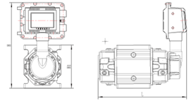
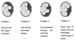
The intelligent Gas Roots Flow Meter is mainly composed of a shell, a conjugate rotor and an intelligent flow integrator. A pair of conjugate rotors installed in the measuring chamber maintain the correct relative position of the rotors through the precision machining adjusting gear under the action of the inlet and outlet pressure difference of the circulating gas (P in > P out). The optimum working clearance is maintained between the rotor, between the rotor and the shell, between the rotor and the wall panel, and continuous non-contact sealing is achieved. For each rotation of the rotor, four times the effective volume of the measuring chamber is output.

Its measurement process and working principle are shown in Figure 2 (only a quarter cycle is shown in the figure).

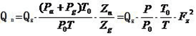
The intelligent flow integrator consists of temperature and pressure detection, flow sensor and microprocessor unit. The microprocessor in the intelligent flow integrator compensates the temperature and pressure according to the gas equation and corrects the compression factor as follows:

············· (1)

In the formula:

Qn: volume flow under standard condition (m3/h);

Qg: volume flow under working condition (m3/h);

Pg: Gauge pressure (kPa) at the pressure detection point of the flow meter;

Pa: local atmospheric pressure (kPa);

Tg: absolute temperature of the medium (273.15+t) (K);

t: Temperature of the measured medium (℃);

Zn: compression coefficient under standard state;

Zg: compression coefficient under working condition;

n: absolute temperature (273.15+20) under standard condition (K);

Pn: Standard atmospheric pressure (101.325kPa).

Note: Natural gas Zn/Zg = Fz2, Fz is called the super compression factor, according to the China National Petroleum Corporation standard SY/T6143-1996 formula to calculate.


Features

  • High-strength aluminum alloy waist wheel, corrosion resistance, anti-aging, long service life, high accuracy, good repeatability
  • Small starting flow, wide range, small pressure loss
  •  No need for a straight pipe section before and after the flowmeter, the measurement accuracy is not affected by pressure and flow changes, and can be installed in a narrow environment
  • Using high-precision digital temperature sensor and digital pressure sensor, and the digital pressure sensor has temperature correction function, high pressure detection accuracy, good long-term stability, small temperature source
  • Large-screen LCD display, the display content is rich and clear
  • Output signal diversification, can be selected according to customer requirements (4 ~ 20) mA standard analog signal, working condition pulse signal, IC card standard volume signal and RS485 communication
  • Intelligent flow integrator can rotate 350 degrees in counterclockwise
  • Direction to facilitate data reading in different directions
  • Integrator LCD display can withstand 80℃ high temperature

Specification

  • Accuracy level:

Level 1.0: QT-Qmax is ±1.0%, Qmin-qt is ±2.0%, where Qt=0.05Qmax.

Level 1.5: QT-Qmax is ±1.5%, Qmin-Qt is ±3.0%, where Qt=0.05Qmax.

  • Basic parameters

Type specification Flow specification Nominal diameter

(mm)

Flow range

(m³/h)

Starting flow

(m³/h)

Maximum pressure loss

(KPa)

ATLQ-25 G16 DN25 1-25 0.05 0.08
ATLQ-40 G25 DN40 1-40 0.05 0.08
ATLQ-50 G25  

DN50

1-40 0.1 0.08
G40 2-65 0.1 0.1
G65 2-100 0.12 0.15
ATLQ-80 G65  

DN80

2-100 0.12 0.15
G100 2.5-160 0.1 0.15
G160 3-250 0.1 0.18
ATLQ-100 G160 DN100 3-250 0.1 0.2
G250 4-500 0.65 0.35
ATLQ-150 G400 DN150 8-650 0.76 0.46
G650 15-1000 0.85 0.5
ATLQ-200 G1600 DN200 32-1600 0.95 0.6
  • Dimensions

Type specification Flow specification L H1 H Remark
ATLQ-25 G16 273 128 340 Note: 1. The flange connection size in the table is PN1.6MPa, and other elements not specified are implemented according to GB/T9119-2010 standard.

2, if you need PN1.6MPa and other standard specifications flange size according to the relevant standard requirements, the outline size please contact the manufacturer customized.

3, when installing, please consider the thickness of the flowmeter and the metal sealing gasket at both ends of the pipe (2~3) mm.

ATLQ-40 G25 354 190 375
ATLQ-50 G25 354 190 375
G40 425 190 375
G65 425 190 375
ATLQ-80 G65 412 190 375
G100 412 190 375
G160 475 245 400
ATLQ-100 G160 575 245 400
G250 665 245 400
ATLQ-150 G400 683 460 505
G650 802 460 505